Because the inverter uses different power supply voltage levels, it is necessary to provide different levels of voltage when maintaining the inverter. However, the real three-phase 200v AC voltage or three-phase 400v AC voltage is not necessarily required for board level maintenance or even chip level maintenance (otherwise, when commissioning with load). What is required is 200v and 400v AC voltage and corresponding 300v and 500v DC voltage. Although there are many types of adjustable DC power supply on the market, they are expensive and the protection function is not ideal. In many years of maintenance work, the author has made a special inverter chip level maintenance power supply with both AC and DC voltage outputs and complete protection functions.
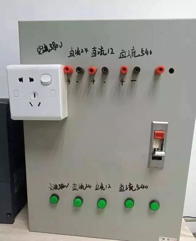
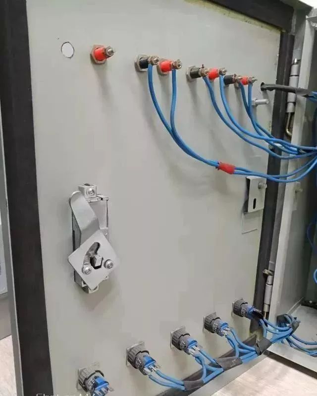
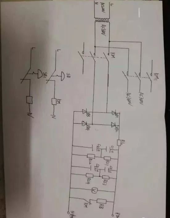
Manufacturing method I of inverter maintenance power supply:
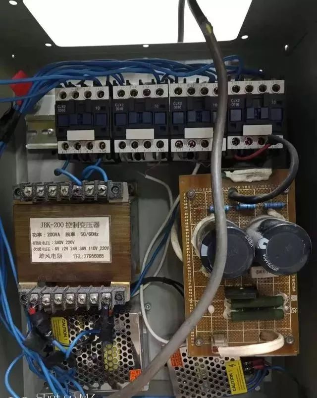
Bill of Materials:
1 AC contactor 220V 32A Quantity: 2
2 Transformer 220V to 380V 500W Single phase Quantity: 1
3 Number of self-locking buttons (position SB SB1) 2
4 Rectifier bridge model MDQ100A Quantity: 1
5 Charging resistor (position RL) 120W60R Quantity: 1
6 Electrolytic capacitor (position C1 C2 C3 C4) 400V680UF Quantity: 4
7. Voltage equalizing resistor (position RC1 RC2 RC3 RC4), resistor 2W180k, quantity 4
8 DC voltmeter, DC1000V pointer type
9 Discharge resistor (position RB) 120W60R Quantity: 1
Drawings:
Method II for making inverter maintenance power supply:
Some maintenance shops, limited by conditions, do not have three-phase maintenance power supply, which brings inconvenience to the maintenance of inverters, especially AC and DC voltage regulators (soft starters) and other electrical equipment.
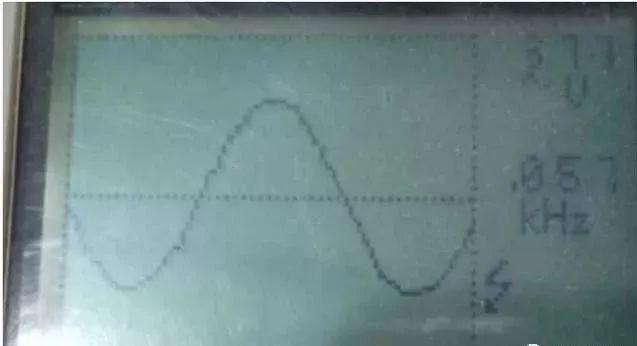
After several tests and reasonable optimization of the structure, a three-phase inverter power supply was made and the output waveform was tested. Hi! Beautiful waveform, very close to the power supply.
As shown in the figure:
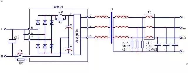
When the frequency converter with 380V three-phase power supply is assembled, the KT1 delay charging circuit shall be added, and its parameters can be the same as those of the internal charging circuit. The isolation transformer adopts 1:1 transformation ratio; If the converter with 220V input power supply is used, the KT1 current limiting link can be omitted, and the 220:380 step-up transformer is used as the isolation transformer. If R2=R1 is selected, the contact capacity of KT1 should be greater than 5A. If it is insufficient, a relay should be added.
As required, T1T2 can be matched according to the output current of the frequency converter. I use the second-hand inverter, isolation transformer and reactor that are idle and easy to get.
If necessary, rectifier filter circuit can be added at the later stage to obtain 0~550V adjustable DC maintenance power supply. When the output waveform is not ideal, try to adjust the carrier frequency of the converter to adapt to the LC filtering time constant, so as to obtain better waveform output.
Post time: Jan-05-2023